I have to admit that the majority of the IT professionals I have met have a little or no idea of basic networking. And sadly some of those are sys admins, site admins, programmers and in the extreme cases even WAN and Network admins and Security “experts”. In the above mentioned group, only the programmers can actually be “excused” . Being a programmer myself, I know that you do not have to be aware of what a Level 4 device is in order to write good code. But it helps… especially in troubleshooting scenarios- for example when your program cannot connect to the database due to network or firewall misconfiguration.
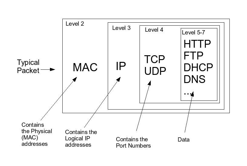
I am a visual person and most of the time a picture speaks a lot more to me than a bunch of words, so here is a simple diagram that explains the basics of a TCP/IP network packet:

A little more detailed version of this diagram I drew up in my notebook when I was taking a networking class in college. I still find myself drawing it on a white board when someone asks me a network question.
The “Level” labels above refer to the different layers of the OSI model. It is helpful to think about a network packet as a present, wrapped in multiple boxes. The outermost box corresponds to level 2 in the OSI model (Data Link layer) and it is the one containing the physical addresses of the source and the destination machines. A typical level 2 device is a network switch.
Inside this big box is the level 3 (Network layer) box that contains the IP address of the computer sending the packet and the one that it is directed to. An example of a level 3 device is a router.
The next box is the one that identifies what port the packet originated from and the number of the port that the destination computer should receive the data on. The port number ultimately determines what application is responsible for processing the data. For example, a packet coming on port 21 means that it is an ftp request and that the ftp daemon on the machine should process it. This box corresponds to level 4 on the OSI model – the Transport layer. A PIX firewall is a typical level 4 network device.
And the innermost box of the packet is the “present” itself – the data. This is what was needed to be delivered from one computer to another on the first place and the rest of the boxes were just the means to accomplish this.
The different network devices and computers open the different boxes and read the information they carry as needed. For example, it is helpful to remember that routers strip the Data Link layer to find out the destination (the IP) address of the packet. Then they reconstruct that layer with a new destination physical address – the MAC address of the next hop on the network and with their own MAC address as the source address. This process repeats until the packet reaches its destination.
I have been asked many times by web programmers how to find out the MAC address of the machine that made the original request . As you can see now- this is impossible. The TCP/IP packet that reaches the web server will only contain the MAC address of the last router that processed the frame.
Of course there is a lot more to network packets and protocols than this. But the simple diagram above is good enough to give you a basic idea and to get someone started in the field of networking.